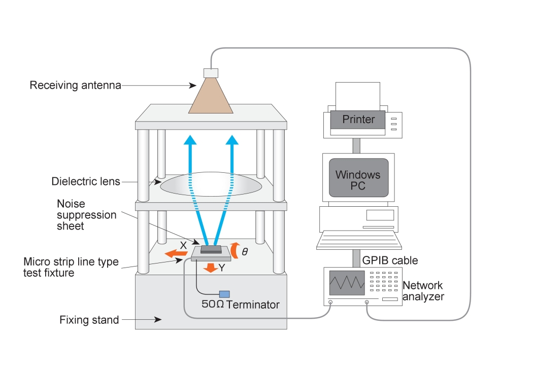
1. Far-field measurement system for electric wave absorber (material), return loss
1.1. Lens antenna method measurement device
|
1.1.1. Lens Antenna Method, Diagonal Incidence Type Electric Wave Absorber, Return Loss Measurement System (2.6-26.5GHz) [EAS03] |
|
|
|
| Detail! |
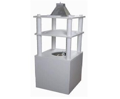
| 1.1.2. Lens Antenna Method, Vertical Incidence Type Electric Wave Absorber, Return Loss Measurement System [EAS07] | |
|
|
| Detail! |
| 1.1.3. Portable Type, Lens Antenna Method, Vertical Incidence Type Electric Wave Absorber, Return Loss Measurement System [EAS12] | |
|
|
| Detail! |
1.2. Wave Pass-Through Thermostat
| 1.2.1. Electromagnetic Wave Transmissive Thermostat Chamber (-60°C ~+200°C) [EMD01] | |
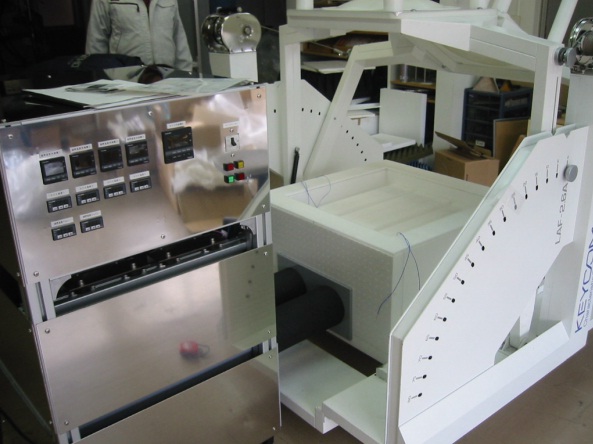
This is a thermostatic chamber for measuring the temperature characteristics of radomes, covers, radio wave absorbers, and shielding effects. It consists of a high/low temperature blower and a heat insulation box to hold a sample for measurement. *Image on the left is a use case with radio wave absorber measurement system(right side), which is NOT included in this product. |
|
| Detail! |
2. Near-Field Noise Suppression Sheet Evaluation System
IEC Standard No.IEC62333-1, IEC62333-2KEYCOM is the front runner of evaluating Noise Suppresion Sheet
In 2003, a Japanese team proposed a standardization of the evaluation method of noise suppression sheet to IEC, and was enacted in 2006.
In the standardization process, KEYCOM participated as a committee member.
- Intra-decoupling ratio: Rda
- Inter-decoupling ratio: Rde
- Transmission attenuation power ratio: Rtp
- Radiation suppression ratio: Rrs
Since then, KEYCOM has been one of the front-runners to develop and commercialize this measurement kit in compliance with the IEC standard.
The systems are used to evaluate radio wave absorbing materials used for preventing oscillation and EMI countermeasure in devices such as mobile phones.
In narrow cases such as smart phone cases, the electromagnetic waves are disorganized and the electric and magnetic fields are independent of each other.
In such a situation, radio wave absorbing material is required to have a large radio wave absorption rate in the near field, not disturbing impedance of the circuit.
As for data to be measured by each system, such as Rda/Rde, Rtp, details can be found in the product links shown below.
Of course, we can propose an optimal system for you, based on your development needs. Please feel free to contact us!
| 2.1. Measure Intra/Inter Decoupling Ratio [Rda/Rde][NSS02] | 2.2. Measure Transmission Attenuation Power Ratio [Rtp][NSS03] | ||
| Detail! | Detail! |
| 2.3. Measure Radiation Suppression Ratio [Rrs-1][NSS05] | 2.4. Measure Radiation Supression Ratio [Rrs-2][NSS04] | ||
| Detail! | Detail! |
3. Software
For Designing Wave Absorber
| 3.1. Single Layer Type / Multi-layer Type, Electric Wave Absorber, Return Loss Simulation Software [EAS01] | |
You can select the two variables you want to optimize among relative permittivity, εr'', relative permeability μr'', sample thickness, and frequency, and let the system run to calculate them. In this way, by repeating various combinations several times, the optimum relative permittivity, relative permeability, or sample thickness can be obtained. |
|
| Detail! |
For Designing Car emblem / Radome
| 3.2. Multilayer plate Simulation software for making designs of emblem and radome [SFW05] | |
|
|
| Detail! |
