How to select the measurement methods
Selecting Dielectric Constant Measurement Method
Select from specimens
| Title | Ref. No. | Frequency | ex) Sample | Feature | |
| 1. | Open type Resonator method | DPS03 | 18GHz~110GHz | Multilayer material Printed board Film(Ultra thin film) Powder Sheet(Board) Radome cover Ceramics Dielectric resonator Ferroelectric |
Resonator method series For low tan delta materials High accuracy Point frequency |
| 2. | TM-mode Perturbation method | DPS18 | 200MHz~10GHz | ||
| 3. | TE-mode Cavity Resonator | DPS19 | 10GHz~40GHz | ||
| 4. | Strip line type Resonance method | DPS50 | 800MHz~14GHz | ||
| 5. | Micro strip line type Resonance method | DPS01 | 800MHz~14GHz | ||
| 6. | Circular Disk type Resonator method | DPS51 | 3GHz~70GHz | ||
| 7. | LC Resonator method | DPS26 | 10MHz, 50MHz, 100MHz | ||
| 8. | Parallel conductor plate type Dielectric resonator method |
DPS14 | 3GHz~26.5GHz | ||
| 9. | Frequency change method | DPS10 | 2.6GHz~110GHz | Multilayer material Printed board Powder Board Phantom Wave absorber Radome cover |
Frequency change method series For low tan delta and thick materials |
| 10. | Frequency change method Coaxial tube and waveguide type | DPS09 | 10MHz~60GHz | ||
| 11. | Probe type (open mode) | DPS16 | 30MHz~90GHz | Multilayer material Sheet(Board) Phantom material Wave absorber Noise suppression sheet Soil Concrete, Asphalt Radome cover Fruit, Vegetable Liquid |
S parameter method series For highr tan delta materials Wide coverage of frequency Permeability is measureable (12, 13. 14) |
| 12. | Probe type (short mode) | DPS25 | 100kHz~10GHz | ||
| 13. | Coaxial Tube and Waveguide Type S-parameter method | DPS08 | 12MHz~40GHz | ||
| 14. | Free space type S-parameter method | DPS24 | 2.6GHz~110GHz | ||
| 15. | Propagation Delay Mode Cut Back Type Coaxial Tube Method |
DPS05 | 45MHz~40GHz | ||
| 16. | Capacitance method | DPS17 | 1Hz~1GHz | Multilayer material Printed board Film(Ultra thin film) Sheet(Board) Phantom material Noise suppression sheet Liquid Ceramics Semiconductor |
Capacitance method series For low frequency High accuracy Wide coverage of frequency |
| 17. | MOSFET structure semiconductor depletion layer And just below the gate electrode dielectric film |
DPS48 | 20Hz~2MHz | ||
| 18. | Ellipsometry method | DPS02 | 26.5~110GHz | Ellipsometry method Dielectric cnstant, permeability measurement |
Select from measurement frequency, dielectric constant, dielectric loss tangent
Select from measurement frequency, dielectric constant, dielectric loss tangentSelect from measurement frequency, method, specimen size
Select from measurement frequency, method, specimen sizeSelect from specific request
The following table is based on FAQ. Please contact us for details.
| When you want to measure an ultra thin film on the printed board with high accuracy (measurement of film, multilayer material) |
» | Perturbation method |
| When your sample is so thin it falls apart without supporting medium (measurement of film, multilayer material) |
» | Perturbation method |
| When high accuracy is the priority (εr' ±1% tanδ ±3%) | » | Perturbation method |
| When you only have a sample as small as 1mm | » | Probe method |
| When you want to measure it in high accuracy by super-high frequency. (20GHz - 110GHz) |
» | Resonance method resonator open type |
| When you want to measure it by super-low frequency.(10μHz - 10Hz) | » | Capacitance method |
| When you want to measure liquid | » | Probe method |
| When you want to measure powder | » | Probe method |
| When you want to measure volatile substance such as gasoline | » | Probe method |
| When you want to change the measurement temperature | » | Capacitance method |
| When you want to sweep frequency and obtain rough result, accuracy is less importan (εr' ± 7% tanδ ± 10%) | » | S-parameter method |
| When you do not want your sample cut or reshaped (Non-destructive) | » | Resonance method micro strip line type |
| When you want the process as simple as possible | » | Probe method |
| When you want to measure dielectric constant, dielectric loss tangent,and permeability at once | » | S-parameter method |
Introduction to KEYCOM's measurement methods
1. Resonance method
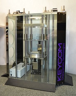
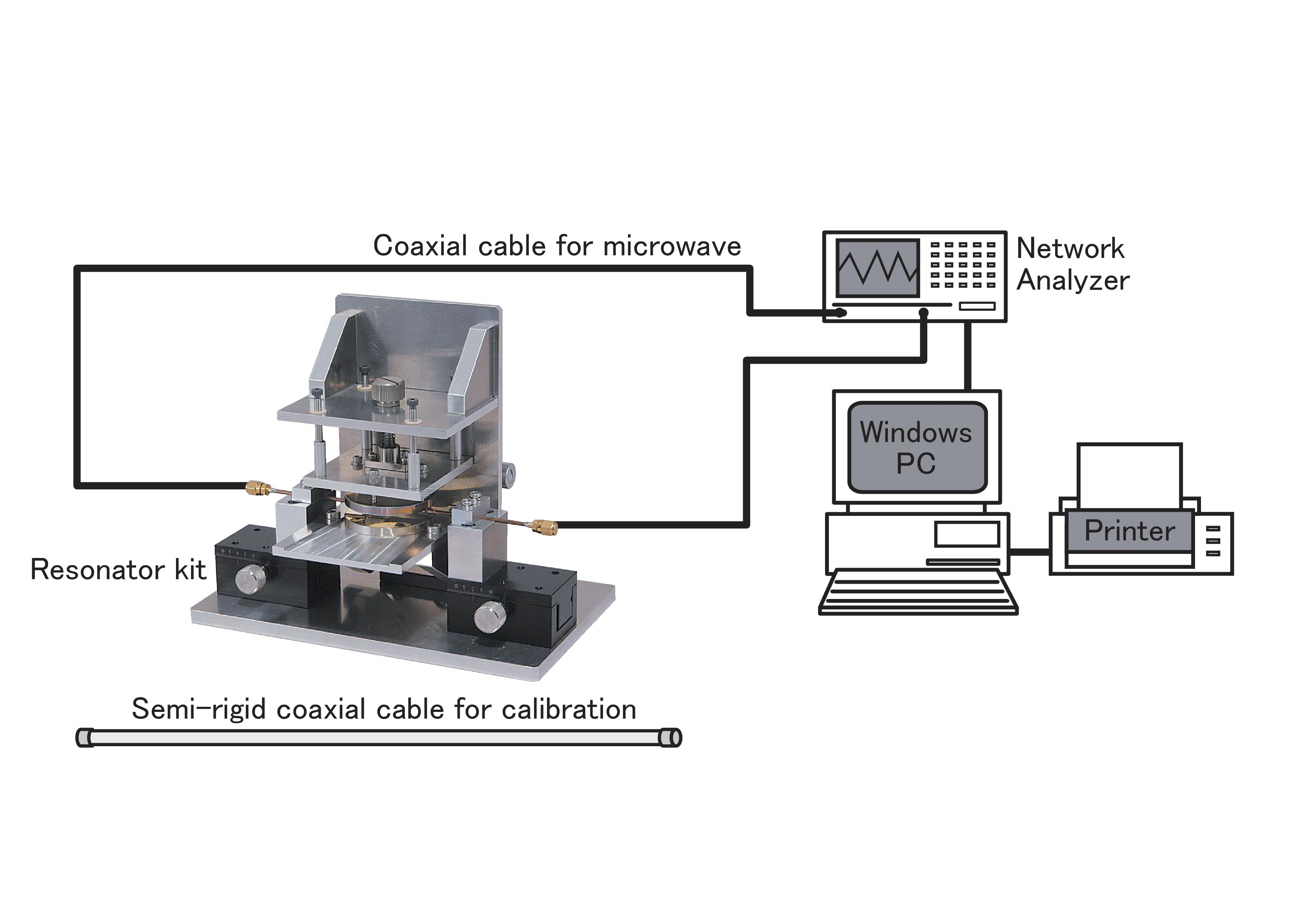
Hiroke Suzuki of Keycom articipated in the drafting of the standard as a member of the committee, and it was officially standardized in the spring of 2004.
| 1.1. Open resonator method for sheet and ultra thin sheet dielectric constant and dielectric loss tangent(millimeterwave) measurement system [DPS03] | |
 It is also ideal for specimens with low tanδ. This method was presented at 2005 IEEE Instrumentation and Measurement Technology Conference Ottawa Ontario, CANADA.
|
|
| Detail! |
| 1.2. Resonance method strip line type for sheet dielectric constant and dielectric loss tangent measurement system [DPS50] |
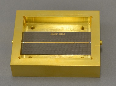 We follow the ASTMD3380-75 Standard method of Test for Permittivity(Dielectric Constant) and Dissipation Factor of Plastic-Based Microwave Circuit Substrates and IPC-L-125 Specification for Plastic Substrates, Clad or Unclad, for High Speed / High Frequency Interconnections. |
| Detail! |
| 1.3. Circular Disk Resonator Type Dielectric Constant and Dielectric Loss Tangent(Dk/Df) Measurement System [DPS51] |
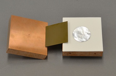 KEYCOM made presentation about the measurement method at IEEE IMS in 2012. [References] Hirosuke Suzuki, Masato Inoue "Complex Permittivity Multi-Frequency Measurements for Dielectric Sheets Using a Circular Disk Resonator". 2012 IMS2012 THPB-1 |
| Detail! |
| 1.4. Resonance method micro strip line type for sheet and ultra thin sheet dielectric constant and dielectric loss tangent measurement system [DPS01] |
|
It conforms to ASTMD3380 Standard method of Test for Permittivity (Dielectric Constant) and Dissipation Factor of Plastic-Based Microwave Circuit Substrates, and IPC-L-125 Specification for Plastic Substrates, Clad or unclad, for High Speed/High Frequency Interconnections. |
| Detail! |
2. Perturbation method
| 2.1. Perturbation method specimen-hole closed type, cavity resonance mode, for ultra thin sheet dielectric constant and dielectric loss tangent measurement system [DPS18] | |
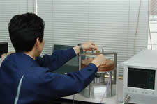 KEYCOM refined the conventional perturbation method that was JIS-standardized in 1992 (JISC2565) by closing the hole into which the specimen is inserted with metal, and the new method is also compliant with ASTMD2520. |
|
|
|
| Detail! |
3. Propagation delay method
| 3.1. Propagation delay mode cut back type coaxial tube method dielectric constant and dielectric loss tangent measurement system [DPS05] |
|
|
| Detail! |
| 3.2. Propagation delay mode Cut Back type Coplanar line method dielectric constant and dielectric loss tangent(Dk/Df) measurement system [DPS07] |
 In the range of 500MHz-65GHz, this system measures dielectric constant and dielectric loss tangent of liquids. It consist of the Cut Back method using a propagation line and the merits are as follows. |
| Detail! |
| 3.3. Propagation delay mode Cut Back type Stripline method dielectric constant and dielectric loss tangent measurement system(Dk/Df) [DPS15] |
It consists of the Cut Back method using propagation lines and has merits below. |
| Detail! |
4. Probe method
| 4.1. Open Mode Probe Method Dielectric Constant and Dielectric Loss Tangent Measurement System(Dk/Df) [DPS16] | |
|
|
| Detail! | |
| 4.2. S-Parameter Method, Probe (Short) Type Relative Permittivity, Dielectric Loss Tangent (Dk/Df), Measurement System [DPS25] | |
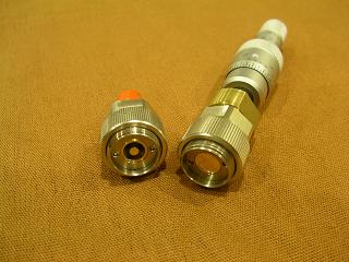 ・Solids and liquids can be used as samples. ・The electric field is perpendicular to the sample surface, which is the same direction as that of microstrip lines and strip lines. ・The electric field is perpendicular to the sample surface, the same direction as the microstrip line and strip line. |
|
| Detail! |
5. S parameter method
| 5.1. S-Parameter Method,Reflection and Transmission Mode,Coaxial Tube and Waveguide Type Dielectric Constant, Dielectric Loss Tangent, Permeability Measurement System [Permittivity, Dk/Df] [DPS08] |
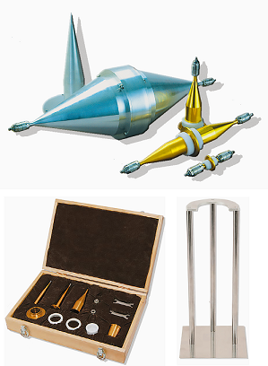 The optional software DMP-70 calculates the absorption ratio and the reflection ratio of electromagnetic absorbers based on the complex εr and complex μr. |
| Detail! |
| 5.2. S-Parameter Method, Free Space Type Dielectric Constant, Dielectric Loss Tangent, Permeability (μ'/μ''), Transmission attenuation, Electric wave absorptance Millimeter wave / Microwave Measurement equipment [εr', tanδ / Dk, Df] [DPS24] |
|
A lens is attached to the antenna, allowing the sample to be measured in a plane wave while remaining compact.The measurement is performed by connecting a vector network analyzer and a computer to the test fixture and observing the S-parameters S21 and S11. |
| Detail! |
6. Capacitance method
| 6.1. Capacitance Method:Dielectric Constant and Dielectric Loss Tangent Measurement System(Dk/Df) for Flat Plate, Liquid, Gel, Ultra-Thin Film, Thin-film Compounds [DPS17] |
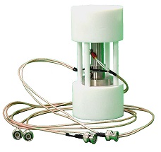 Different types of electrodes are available for specific states of specimens; DPT-009 for plate, thin film, gel, DPT-012, DPT-013-050 and DPT-013-200 for liquid, and DPT-2141 for ceramic insulators. |
| Detail! |
7. Incident Angle Changing Method
| 7.1. Angle of Incidence Change Method Dielectoric Constant, Dielectric Loss Tangent, Permeability(Dk/Df) Measurement System [DPS22] |
|
Unlike the coaxial tube and waveguide types, the sample is not placed inside the fixture, so there is no air gap error. Since a lens is attached to the antenna, the sample can be measured as a plane wave despite its compact size, and high measurement accuracy can be obtained. Radio wave emitted from the antenna is a parallel beam, so the sample can be made smaller.In addition, εr' and μr can be obtained for each frequency. *Measurements can be made without an anechoic chamber. |
| Detail! |
8. Transmission Attenuation Method
| 8.1. Millimeter Wave, Permittivity, Dielectric Loss Tangent and Transmission Attenuation Measurement System [RTS02] | ||||
|
The relative dielectric constant and tan δ are obtained from the relationship between the frequency and the transmission attenuation when millimeter waves pass through a flat plate.
👉Note: The higher the frequency, the smaller the sample can be measured. Using a standard vector network analyzer and applying GATE beyond the lens after calibration, transmission attenuation can be measured with a resolution of 0.1 dB and dielectric constant of 0.01.Scalar network analyzers and synthesized sweepers can also be used. |
||||
| Detail! |
| 8.2. Microwave, Permittivity, Dielectric Loss Tangent and Transmission Attenuation Measurement System [RTS04] | ||||
|
The relative dielectric constant and tan δ are obtained from the relationship between the frequency and the transmission attenuation when millimeter waves pass through a flat plate.
👉Note: The higher the frequency, the smaller the sample can be measured. Using a standard vector network analyzer and applying GATE beyond the lens after calibration, transmission attenuation can be measured with a resolution of 0.1 dB and dielectric constant of 0.01.Scalar network analyzers and synthesized sweepers can also be used. |
||||
| Detail! |
| 8.3. Microwave, Vertical Type Permittivity (Dielectric constant), Dielectric Loss Tangent and Transmission Attenuation Measurement System [RTS03] |
|
| Detail! |
9. Other measurement methods
| 9.1. Parallel Conductor Plate Type, Dielectric Resonator Method, Dielectric Constant and Dielectric Loss Tangent Measurement System(Dk/Df) [DPS14] |
 |
| Detail! |
| 9.2. Ellipsometry Method, Dielectric Constant and Permeability Measurement System(Dk/Df) [DPS02] |
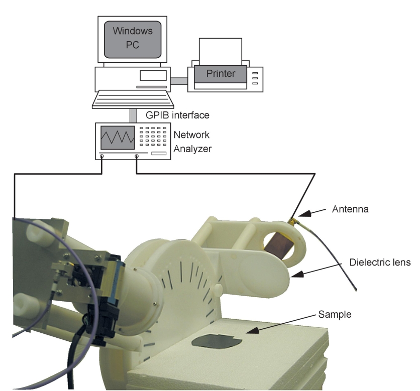 By measuring the amplitude ratio and phase difference between the TE and TM waves of the reflection coefficient, the complex relative permittivity and complex permeability can be determined. Unlike the coaxial tube and waveguide types, the sample is not placed inside the fixture, so errors due to air gaps do not occur. A lens is attached to the antenna, making it compact and allowing the sample to be measured in a plane wave. In addition, the sample can be set near the antenna, making the sample smaller. In addition, εr and μr can be obtained for each frequency. |
| Detail! |
| 9.3. Cutoff Cylinder Waveguide For Millimeter-wave measurement of Relative Permittivity and Dielectric Loss Tangent (εr', tanδ) [DPS20] |
|
|
| Detail! |
| 9.4. Capacitance Measurement System (10kHz~110GHz) [CAP01] |
 |
| Detail! |
