1. Radome, Emblem, Radar cover evaluation
|
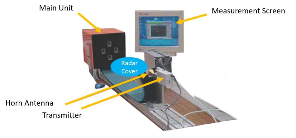
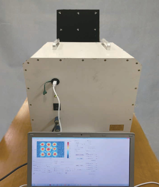
1.1. Emblem/Radar cover Evaluation System [EES01A] One-way type, applicable to production line |
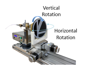
1.2. Emblem/Radar cover Evaluation System [EES04] One-way type, varaiable sample setting angle |
||
|
|
||
| Detail! |
Detail! | ||
|
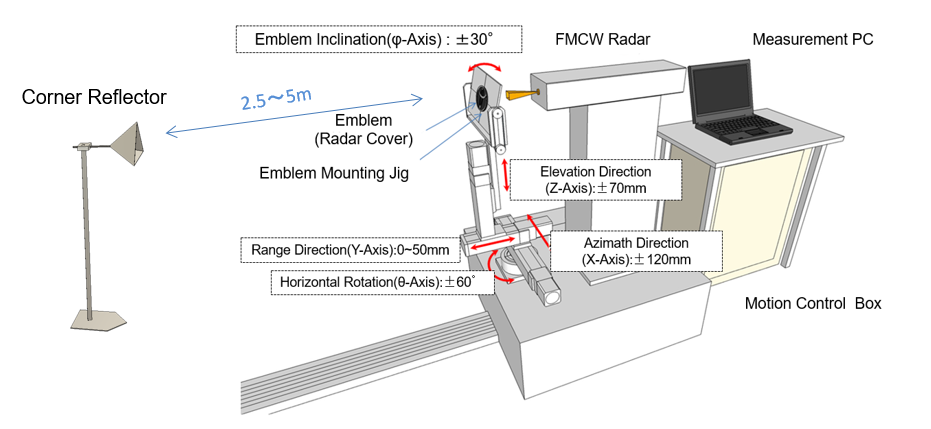
1.3. Emblem/Radar cover Evaluation System [EES12-01] Two-way type, variable sample setting angle/position |
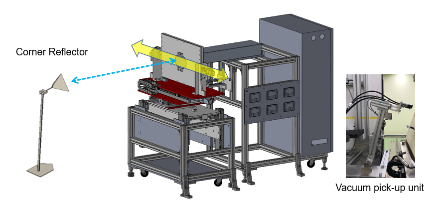
1.4. Emblem/Radar cover Evaluation System [EES12-02] Two-way type, applicable to production line |
||
|
The system can measure transmission attenuation and tilt angle of each irradiation point on the sample such as an emblem in the following cases. (1)when the sample moves in any direction (Azimath, Range, Elevation) |
|
||
| Detail! |
Detail! |
|
1.5. Emblem/Radar cover Evaluation System [EES13] One-way type, reflection attenuation |
1.6. Emblem/Radar cover Evaluation System [EES14] Two-way type, reflection attenuation |
||
|
|
||
| Detail! |
Detail! | ||
| 1.7. Millimeter Wave Cover Beam Tilt Distribution Measurement System [RCS10] |
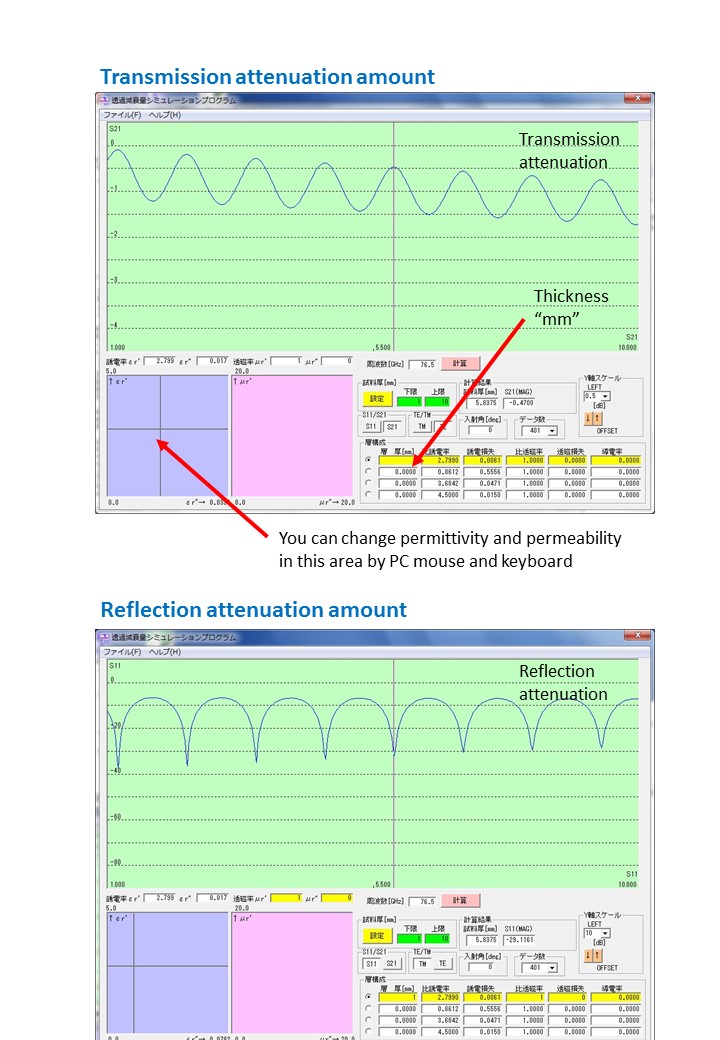
1.8. Simulation software for designing emblem [SFW05] |
||
|
|
||
| Detail! | Detail! |
2. Far-field Transmission Attenuation measurement system
| * No anechoic chamber required | |||
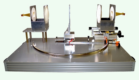
| 2.1. Millimeter wave/Micro wave Radorm for radar and cover Transmission attenuation measurement system [RTS01] | 2.2. Free Space Type Dielectric Constant, Dielectric Loss Tangent, Transmission attenuation (Permittivity, Dk/Df) Measurement equipment [DPS10] | ||
|
|
||
| Detail! | Detail! | ||
