Bias-TEE For Large Current
Model No. BYT05
Specifications
| Model No. |
BYT05(35A) |
BYT05(15A) |
BYT05(20A) |
| Parts No. |
KDC-H100K1G-35A |
KDC-H100K6G-15A |
KDC-H100K2G-20A |
| RF Frequency |
100kHz-1GHz |
100kHz-6GHz |
100kHz-2GHz |
| RF Insertion Loss |
2dB |
5dB |
2dB |
| RF Maximum input/output power |
30dBm |
30dBm |
30dBm |
| RF Return Loss(min) |
15dB |
8dB |
15dB |
| DC Withstand Voltage |
10V |
20V |
20V |
| DC Maximum Supply Current |
35A |
15A |
20A |
| Connector: RF I/O side |
SMA(f) |
SMA(f) |
SMA(f) |
| Connector: RF+DC I/O side |
N(f) |
N(f) |
N(f) |
| Connector : Power supply DC |
Banana Jack : Red VDD/ Black GND |
Banana Jack : Red VDD/ Black GND |
Banana Jack : Red VDD/ Black GND |
| Size |
100(W)x250(D)x150(H)mm |
100(W)x250(D)x150(H)mm |
320(W)x230(D)x149(H)mm |
| Warm-up time |
30 min(Recommended) |
30 min (Recommended) |
30min(Recommended) |
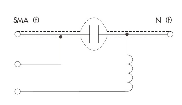
Configuration
Case of single bias-tee
Case of connecting two identical bias-tees
 |
When using a vector network analyzer, conduct calibrations of Open, Short and Load instead of DUT. Then, when two bias - tees are directly connected, S11 and S21 are as follows:
- S11: ‒30 dB or less (100 kHz to 6 GHz / 15 A, 100 kHz to 1 GHz / 30 A)
- S21: 1 dB or less (100 kHz to 6 GHz / 15 A, 100 kHz to 1 GHz / 30 A)
Damage avoidance in the case of connecting to a network analyzer. Insulation between RF input and RF output should be surely confirmed before the maximum DC power supply current flows.
|

