Contents
Dielectric constant (permittivity, εr') and dielecric loss tangent (tan δ) measurement system
Resonance method (JIS enacted open-type resonance method JIS R 1660-2) |
|
| Open resonator method for sheet and ultra thin sheet dielectric constant and dielectric loss tangent (millimeterwave) measurement system | |
| dps03002990714-18 | |
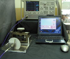
| This system can measure εr and tan δ of ultra-thin films. It employs a Fabry-Perot resonator having an open resonator allowing it to achieve a high measurement accuracy in the millimeter-wave frequency range and also ensuring easy access to the specimen hold plate. In addition, it has the advantage that it can measure specimens having a low tan δ. Measurements are automatically controlled using PC having a with Windows operating system. These features were presented at the 2005 IEEE Instrumentation and Measurement Technology Conference. This method was adopted as a JIS standard (JIS R 1660-2:2004) in 2004. |
|
|
|
| Resonance method strip line type for sheet dielectric constant and dielectric loss tangent measurement system | |
| dps50002070405-07 | |
| In frequency range from 800MHz to 14GHz, it is the measurement system of εr'and tanδ , for sheet material of small dielectric loss tangent and 1-40 εr'. We follow the ASTMD3380-75 Standard method of Test for Permittivity (Dielectric Constant) and Dissipation Factor of Plastic-Based Microwave Circuit Substrates and IPC-L-125 Specification for Plastic Substrates, Clad or Unclad, for High Speed / High Frequency Interconnections. |
|
| Resonance method micro strip line type for sheet and ultra thin sheet dielectric constant and dielectric loss tangent measurement system | |
| dps01002000313-08 | |
| This is a measurement equipment and system which measures εr and tanδ of the material that the dielectric substance loss is comparatively small, and εr is roughly 1 from 40 in the frequency being from 800MHz to 14GHz. It is a measurement kit that conforms to ASTMD3380-75 Standard method of Test for Dielectric Constant and Dissipation Factor of Plastic-Based Microwave Circuit Substrates, IPC-L-125 Specification for Plastic Substrates, Clad or Unclad, and for High Speed/High Frequency Interconnections and it can measure εr and tanδof the ultra thin dielectric substance sheet. |
|
Perturbation method |
|
| Perturbation method specimen-hole closed type, cavity resonance mode, for ultra thin sheet dielectric constant and dielectric loss tangent measurement system | |
| dps18002031022-11 | |
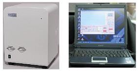
This is a high precision perturbation measurement instrument that measures a specimen's dielectric constant (εr') and dielectric loss tangent (tan δ) in the microwave region. In accordance with the method prescribed by JIS standards (JISC2565 in 1992), "KEYCOM" has improved measurement accuracy by closing the hole into which the specimen is inserted with metal.
|
|
Propagation delay method |
|
| Propagation delay mode cut back type coaxial tube method dielectric constant and dielectric loss tangent measurement system | |
| dps05002981027-10 | |
| In the 45 MHz-40 GHz frequency range, this system measures permittivity (dielectric constant, εr) and dielectric loss tangent (tan δ) of liquids having εr of approximate 1.05-500. It can also estimate the voltage dependence of εr and tan δ for samples such as liquid crystals by applying a bias voltage during the measurement. | |
| Propagation delay mode cut back type Free space method dielectric constant and dielectric loss tangent measurement system | |
| dps06002000831-05 | |
| In the 45 MHz-40 GHz frequency range, this system measures dielectric constant/permittivity and dielectric loss tangent of the materials which have dielectric constant of approximate 1.05-500. Especially it greatly contributes to large loss specimens | |
| Propagation delay mode Cut Back type Coplanar line method dielectric constant and dielectric loss tangent measurement system | |
| dps07002010619-24 | |
| This system measures the permittivity (dielectric constant, εr) and the dielectric loss tangent (tan δ) of liquids and powdered materials in the 500 MHz - 65 GHz frequency range. In liquid measurement, a sample covers a coplanar line to a thickness of approximately 0.2 mm. The εr and tan δ values of the liquid sample are then calculated from the actual εr and tan δ values of the dielectric complex consisting of the liquid and the coplanar line, using installed simulation software that simulates the electromagnetic field of a coplanar line. In addition, the voltage dependence of εr and tan δ for samples such as liquid crystals can be estimated by applying a bias voltage during the measurement. | |
| Propagation delay mode Cut Back type Stripline method dielectric constant and dielectric loss tangent measurement system | |
| dps15 | |
In the 45 MHz-40 GHz frequency range, this system measures permittivity (dielectric constant, εr) and dielectric loss tangent (tan δ) of dielectric substance sheets and clayey materials, etc. For the measurement of powdered materials, we can provide an optional software which calculates the true εr and tan δ using a bulk specific gravity and a absolute specific gravity, and can also do a temperature measurement equipment and a calculation software of temperature dependency. The voltage dependence of εr and tan δ can be estimated by applying a bias voltage during the measurement. |
|
Probe method |
|
| Open mode probe method dielectric constant and dielectric loss tangent measurement system | |
| dps16002021001-11 | |
| * Measurement frequency can be select in a wide range, 200 MHz - 90GHz. * Solid, liquid, and powdered materials can be measured. * Standard specimen other than pure water can be available (ex. acetone and ethanol). * simple to operate
|
|
Angle of incidence change method |
|
| Angle of incidence change method dielectoric constant, dielectric loss tangent, permeability measurement system | |
| dps22002040516-08 | |
| This system can measure the dependency on angle of incidence of the magnitude and phase of the reflection coefficient in both the TE wave and the TM wave. Complex relative permittivity and complex permeability are estimated from these measured values. Unlike the coaxial-tube-type or a waveguide-type methods, this method does not involve errors caused by air-gaps since the specimens are not installed in a fixture. Moreover, the lens attached to antenna enables to measure samples with plane wave, resulting in the high measurement accuracy. In addition, this method using a parallel beam from a antenna can reduce the size of a specimen. In all frequency range,. εr and μr can be obtained. |
|
Capacitance method |
|
| Capacitance method, flat plate, liquid, gel, ultra thin film, compound film, dielectric constant and dielectric loss tangent measurement system | |
| dps17002040705-04 | |
| It is a system that measures the dielectric constant and dielectric loss tangent, factor of a flat plate, the liquid, and the gel. (It is possible to correspond from the room temperature to 200 degree.) When we measure a ultra thin film, a film on the semiconductor wafer and a film, we use electrode DPT-009 for measurement and an assistant for electrodes. It has the interface that controls the external with CPU. |
|
S parameter method |
|
| S-parameter method, reflection and transmission mode, coaxial tube and waveguide type dielectric constant, dielectric loss tangent, permeability, measurement system | |
| dps08002011118-07 | |
| This measurement equipment enables 2 different kinds of measurement methods of the reflection and the transmission, one of which can be chosen depending on the purposes. Either method makes it possible to measure complex dielectric constant and complex ur at the same time. How to select one of the 2 methods is as follows. Also an absorption ratio and a reflection ratio of the electromagnetic absorber can be obtained by calculating complex dielectric constant and complex μr. |
|
| S-parameter method Free space type transmission mode for flat plate dielectric constant and permeability measurement system | |
| dps21002040614-08 | |
| Unlike a coaxial tube type or a wave guide tube type, this method does not make errors caused by air-gap because specimens are not put into a fixture. Practical data can be obtained even at the rough, uneven surfaces where the specimen is placed on. It enables compactness and measuring specimens by flat-wave because of direct installment of lens with an antenna. Measurement is achieved by monitoring S21 & S11 parameter with connections of a test fixture to a vector network analyzer and PC. |
|
Others |
|
| Parallel conductor plate type dielectric resonator method dielectric constant and dielectric loss tangent measurement system | |
| dps14002021001-11 | |
| This is a highly accurate measurement equipment mainly measures εr and tanδ in the micro wave band of the low loss material. It uses a columnar shape specimen. Moreover, this is a measuring method provided in JIS standard as JIS R 1627. | |
| Eripsometore method, dielectric constant and permeability measurement system | |
| dps02002051012-05 | |
| Because it is a scalar measurement, an expensive vector network analyzer is not required. Moreover, dielectric constant compared with source and permeability compared with source can be requested by measuring the difference between TE TM wave of the reflection coefficient and amplitude ratio of the wave and phase. It is unlike coaxial tube or waveguide, and the error by the airgap doesn't occur because it doesn't put the sample in Ficscha. In addition, it is compact size because it installs a lens to an antenna. However, you can measure a sample by plane wave. And, the sample can be reduced, because the sample can be set in the antenna neighborhood. And, you understand εr' and μr every frequency |
|
Permeability (μr') measurement system
| S-parameter method Reflection and transmission mode coaxial tube and waveguide type dielectric constant, dielectric loss tangent, permeability, measurement system |
| dps08002011118-07 |
| This measurement equipment enables 2 different kinds of measurement methods of the reflection and the transmission, one of which can be chosen depending on the purposes. Either method makes it possible to measure complex dielectric constant and complex ur at the same time. How to select one of the 2 methods is as follows. Also an absorption ratio and a reflection ratio of the electromagnetic absorber can be obtained by calculating complex dielectric constant and complex μr. |
| S-parameter method Free space type reflection mode for flat plate dielectric constant and permeability measurement system |
| dps09002981027-08 |
| Unlike the coaxial-tube-type or a waveguide-type methods, this method does not involve errors caused by air-gaps since the specimens are not installed in a fixture. Practical data can be obtained even when the specimen is placed on a rough, uneven surface. It is compact and allows specimens to be measured by flat-wave because of the direct installment of lens with an antenna. It performs measurements by monitoring the S11 parameter via connections of a test fixture to a vector network analyzer and a PC. |
| S-parameter method Free space type transmission mode for flat plate dielectric constant and permeability measurement system |
| dps21002040614-08 |
| Unlike a coaxial tube type or a wave guide tube type, this method does not make errors caused by air-gap because specimens are not put into a fixture. Practical data can be obtained even at the rough, uneven surfaces where the specimen is placed on. It enables compactness and measuring specimens by flat-wave because of direct installment of lens with an antenna. Measurement is achieved by monitoring S21 & S11 parameter with connections of a test fixture to a vector network analyzer and PC. |
| Angle of incidence change method, dielectoric constant, dielectric loss tangent, permeability measurement system |
| dps22002040516-08 |
| It can be measured the dependency on angle of incidence of the magnitude and phase of the reflection coefficient in both the TE wave and the TM wave. Complex relative permittivity and complex permeability are estimated from these measured values. Unlike the coaxial-tube-type or a waveguide-type methods, this method does not involve errors caused by air-gaps since the specimens are not installed in a fixture. The lens attached to antenna enables to measure samples with plane wave, resulting in the high measurement accuracy. This method using a parallel beam from a antenna can reduce the size of a specimen. In all frequency range,. εr and μr can be obtained. |
| Eripsometore method, dielectric constant and permeability measurement system |
| dps02002051012-05 |
| Vector network analyzer is not required, as it is a scalar measurement. Dielectric constant compared with source and permeability compared with source can be measured the difference between TE TM wave of the reflection coefficient and amplitude ratio of the wave and phase. Unlike coaxial tube or waveguide, and the error by the airgap doesn't occur as it doesn't put the sample in Ficscha. It is compact size installing a lens to an antenna. You can measure a sample by plane wave. As the sample can be set close to the antenna, the sample will be small in size, you can read εr' and μr at frequency. |
Magnetic property characteristic measurement system
| Magnetic property characteristics measurement system |
| per01002050701-01 |
 It is a system measuring complex permeability μr'- jμr'' of the magnetic material and ferromagnetic resonance relaxation coefficient α, resonant line width ΔH, and saturation magnetization 4πMs in wideband. It is a system measuring complex permeability μr'- jμr'' of the magnetic material and ferromagnetic resonance relaxation coefficient α, resonant line width ΔH, and saturation magnetization 4πMs in wideband. The disc or the square slab specimen is set to the shorted microstrip line, and it can be measured with a vector network analyzer by sweeping frequency range. It can be measured from 1MHz to 16GHz. |
| ESR measurement system for magnetic property |
| esr05002061101-07 |
 This system is for the magnetic materials, especially the best for the research such as Spintoronics and Quantum dots technology. This system is for the magnetic materials, especially the best for the research such as Spintoronics and Quantum dots technology. ・ It has the measurement sensitivity more than that of standard type X band ESR system, because it uses ferromagnetic resonance(FMR) . ・ You can rotate the specimen by two axis accurately, and can incline the specimen. ・ You can change the static magnetic field from zero to high magnetic field up to 500 mT. |
Electric wave absorption rate measurement system (in near-field / in far-field)
Software
| Single layer type / Multi layer type : Electric wave absorber , Return loss, Simulation soft |
| eas01002010910-0 |
| Two variables are to optimize among εr', εr'', μr', μr'', thickness of specimen and the frequencies. The distribution of the amount of the return loss is shown, as the line of the figure below. You will find most suitable εr, μr, specimen thickness repeating several times various combinations. |
Electric wave absorber (material), return loss measurement system
Diagonal incidence type
| Lens Antenna Method, Diagonal incidence type electric wave absorber (material), return loss measurement system (for 2.6-26.5GHz) |
| eas03002010704-01 |
It is suitable for the evaluations of the electric wave absorption material and the shield material, etc. |
| Lens Antenna Method, Diagonal incidence type for millimeter wave, desk top model electric wave absorber (material), return loss measurement system (for 26.5-110GHz) |
| eas0500201609-05 |
It is for evaluation of the electric wave absorption material. |
vertical incidence type
| Lens Antenna Method, Vertical incidence type electric wave absorber (material), return loss measurement system |
| eas07002981027-10 |
| The error by the airgap doesn't occur, because the measurement system doesn't put the sample in Ficcha, unlike the coaxial tube type or waveguide type. The antenna can be mounted on the lens, compact even though the plane wave samples can be measured. The sample can be smaller, because we can set a sample closed to the antenna. |
| Handy type Lens Antenna Method Vertical incidence type, electric wave absorber (material), return loss measurement system |
| eas12002041115-12 |
| It is a portable type, about the "Lens Antenna Method, Vertical incidence type electric wave absorber (material), return loss measurement system". After the electric wave absorber is installed, the amount of the reflection can be measured. It can be detected influence such as the joints because you can move an antenna easily. The error by the airgap doesn't occur, because the measurement system doesn't put the sample in Ficcha, unlike the coaxial tube type or waveguide type. The antenna can be mounted on the lens, compact even though the plane wave samples can be measured. The sample can be smaller, because we can set a sample closed to the antenna. |
For low frequency
| For low frequency, micro strip line method electric wave absorber (material), return loss measurement system |
| eas08002020721-05 |
The amount of the reflection attenuation of the electric wave absorber for the MHz belt can be measured with a small sample. |
For near-field
Noise suppression sheet characteristics, evaluation system (electric wave absorption material measurement system)
| For near-field noise suppression sheet evaluation system Intra / inter・ decoupling ratio measurement system (Rda・Rde measurement system) IEC standard No.:IEC62333-1, IEC62333-2 |
| nss02 |
| Regarding the evaluation method of the noise suppression seat, Japanese team suggested standardizations to IEC in 2003, and it was enacted in May, 2006. ("KEYCOM" participated as a committee member) "KEYCOM" has commercialized the measurement kit based on this evaluation method. It is for the evaluation of electric wave absorption materials to use for prevention of oscillation and an anti-EMI measure of a mobile telephone. The electromagnetic wave is disorderd in the narrow cases, and an electric field and a magnetic field become independent. As for the electric wave absorption material in such a situation, the electric wave absorption rate in the near field should be large. It is unnecessary to disarrange the impedance of the circuit. |
| For near-field Noise suppression sheet evaluation system Transmission attenuation power ratio measurement system (Rtp measurement system) IEC standard No. : IEC62333-1, IEC62333-2 |
| nss03 |
| Regarding the evaluation method of the noise suppression seat, Japanese team suggested standardizations to IEC in 2003, and it was enacted in May, 2006. ("KEYCOM" participated as a committee member) "KEYCOM" has commercialized the measurement kit based on this evaluation method. It is for the evaluation of electric wave absorption materials to use for prevention of oscillation and an anti-EMI measure of a mobile telephone. The electromagnetic wave is disorderd in the narrow cases, and an electric field and a magnetic field become independent. As for the electric wave absorption material in such a situation, the electric wave absorption rate in the near field should be large. It is unnecessary to disarrange the impedance of the circuit. |
| For near-field Noise suppression sheet evaluation system For anechoic chamber Radiation Suppression ratio measurement system (Rrs measurement system) IEC standard No. : IEC62333-1, IEC62333-2 |
| nss04 |
| Regarding the evaluation method of the noise suppression seat, Japanese team suggested standardizations to IEC in 2003, and it was enacted in May, 2006. ("KEYCOM" participated as a committee member) "KEYCOM" has commercialized the measurement kit based on this evaluation method. It is for the evaluation of electric wave absorption materials to use for prevention of oscillation and an anti-EMI measure of a mobile telephone. The electromagnetic wave is disorderd in the narrow cases, and an electric field and a magnetic field become independent. As for the electric wave absorption material in such a situation, the electric wave absorption rate in the near field should be large. It is unnecessary to disarrange the impedance of the circuit. |
| Noise suppression sheet characteristics evaluation system (For near-field, Electric wave absorption material measurement system) Anechoic chamber is not required, Radiation suppression ratio measurement system (Rrs measurement system) IEC standard No. : IEC62333-1, IEC62333-2 |
| nss05 |
It can be measured without anechoic chamber. |
Penetration attenuation measurement system
| Millimeter wave, micro wave Redorm for radar and cover Transmission attenuation measurement system |
| rts 01002040523-02 |
| It can be easily measured, the attenuation of radar wave when it transmits redorm and cover. Oprimun thickness of a flat dielectric material at required frequency is calculated by changing frequency. It is compact in size, and the lens can be mounted on the antenna. It can be measured high accuracy, as the sample can be measured by plane wave. The sample can be smaller, as we can be set a sample closed to the antenna. |
| Micro wave, vertical type Permittivity (Dielectric constant), dielectric loss tangent and transmission attenuation measurement system |
| rts 03 |
| It is capable to measure from 5GHz to 26.5GHz Permittivity and dielectric loss tangent are given in relation with transmission attenuation loss and frequency passing through flat plate. 1) Measurement value will be average value. 2) This system is not for reflection attenuation loss of absorption materials. Feature is no error by airgap, as this is no samples in the test fixture. It is compact in size and is capable of measuring sample by plain wave. |
Shield effect measurement system
| Coaxial tube type Effect of shield measurement system (12.0MHz~18.0GHz) |
| sem01002011015-01 |
| This system conforms to ASTM D4935. It measures the effect of shield at high accuracy by the plane wave. * There is a dynamic range of 100dB or more. * It is for coaxial tube, 153D, 39D, 20D, and the GPC7 type. * You can keep the file data in Excel format and can reproduce a graph with this. |
| Waveguide type Effect of shield measurement system (1.0GHz~90.0GHz) |
| sem02002011015-01 |
| This system can be measured the shield effect of the specimen at wide range. It is 100dB dynamic range at 1GHz~40GHz,and 70dB dynamic range at 40GHz~90GHz. It is waveguide structure, an incidence angle of the plane wave to the specimen changes every frequency. Therefore, you can measure relations between an incidence angle to the specimen of the plane wave and effect of shield. |
| For cable Effect of shield measurement system |
| sem03002011015-01 |
| This system is a standard measurement method, that conforms to MIL-C-85485A. It is effective to the evaluation of the coaxial cable and the multi core cable. It can be corrected it by the value of the characteristic impedance. |
| Crosstalk type For cable Effect of shield measurement system |
| sem 04002021210-03 |
| It is based on the crosstalk method, and the effect of the shield can be easily measured. It supports from a coaxial cable to multi core cable. It prevents mismatting by the characteristic impedance difference with a pad of 10dB. |
ESR (electron spin resonance) measurement system
| W-band, ESR (electron spin resonance) measurement system (helium-free type) |
| esr01002021207-11 |
| This system is the W-band ESR (electron spin resonance) spectrometer device which is highly sensitive. It is a helium free type, the injection of helium is not required. We used the dielectric substance waveguide for the millimeter-wave waveguide employing new concept. |
| X-band, ESR (electron spin resonance) measurement system |
| esr02002021207-12 |
| This system is the X-band ESR (electron spin resonance) measurement system which is highly sensitive. A free radical can be easily measured. It is possible to use widely as an analysis device and an evaluation device, in the biochemistry field and environmental science field. |
| Desk-top type ESR (electron spin resonance) measurement system (compact, transportable, measurement place specification, high sensitivity) |
| esr04002060505-02 |
| It is very compact desk-top type ESR measurement device, and it is easy to use on the site. It has higher sensitivity than standard type X-band ESR measurement device. It is a small model of 27kg in weight by using the rare earths magnet. You can install the automatic liquid transportation unit by the option. It can perform the mixture measurement of the water solution sample and analysis by PC control. It can be used for the process monitoring, for desk-top ESR sensor, and for remote control, etc. * Single purpose specification - It is designed the magnetic field and the frequency according to the purpose. |
| Alanine dosimetry ESR(EPR) equipment |
| esr31 |
| It is the single purpose specifications portable ESR( electron spin resonance) device which KEYCOM Co., Ltd. developed. It is a type for alanine dosimetry. It specialized a measurement object in an alanine origin radical. It conforms to JIS standard (JIS Z4571). It is the device which is more compact for high sensitivity than the general-purpose ESR device by setting microwave frequency in 9.8GHz, 350 resonance magnetic field mT. In addition, I realized thorough PC control and succeeded in what I used the Mn2+ signal which became inside standard and adopted for revision of magnetic field strength and the absorption strength. |
| Specimen rotation, Inclination type, Static magnetic field is variable widely, ESR (electron spin resonance) measurement system |
| esr05002061101-07 |
| This system is the best for the research such as Spintoronics. ・ It has the measurement sensitivity more than standard type X band ESR system. ・ You can rotate by two axis the specimen with accuracy, and can incline the specimen slightly. ・ You can change the static magnetic field, from zero magnetic field to high magnetic field. |
Test fixture
| Millimeter wave/ microwave test fixtures Micro strip line/ Coplanar line type TRL calibration kit |
| mtf01002021130-01 |
| KEYCOM have prepared the test fixtures to 110GHz. It is used for the pattern performance test between edges of printed-circuit board (edge type), or used for the circuit test in printed-circuit board (probe type). It is the calibration kit for Vector Network Analyzer, by the "through" "open" and "line" mode. |
| Coaxial type, open / short / load |
| mtf02002030111-09 |
| "Open" and "Short" have been adjusted the same distance from the edge of the connector. |
| Tunable short (Metallic waveguide) |
| mtf03002020710-09 |
| It is the tunable short for a rectangular waveguide. There is no instability by defective noncontact because the short side is a noncontact type. |
Standard specimen
| Standard specimen |
| sts01002020101-01 |